Ao 9.00 Antenna Optimizer Program

Electromagnetic waves are in a sense a bit mysterious: You cannot see them, not smell nor touch them. Bmw Fsc Code Keygen Torrent. Nevertheless, the propagation of electromagnetic waves is greatly influenced by surrounding objects and media.
- An Introduction To Computer Science Using C John Carter Pdf Viewer - Horse Handicapping Software - Quake 3 Arena Full Version Free Pc - Demarrage Par Auto Transformateur Pdf Download - Ao 9.00 Antenna Optimizer Program - Izotope. Warning: Invalid argument supplied for foreach() in /srv/users/serverpilot/apps/jujaitaly/public/index.php on line 447. 1 I celebrate myself, and sing myself, And what I assume you shall assume, For every atom belonging to me as good belongs to you. I loafe and invite my soul. Ao 9.00 Antenna Optimizer Program.
The performance of an antenna, and in particular its radiation pattern, is therefore difficult to visualise, interpret and measure in an objective way. Additionally, there are (almost) no closed-form formulas for designing antennas. Antennas are usually designed in an iterative trial and error process, often comparable with Darwinian organic evolution, in which certain aspects of partially successful designs are combined in the hope of producing a more successful design. Antenna synthesis software based on this principle employ, what is called, a genetic algorithm (GA). There is little need to say that the alternative to this, which is: repetitive building, installing and measuring antenna design variations is very time- and material consuming.
Both problems are to a great extent overcome with computer-aided antenna modelling. As a bonus, you will be eager to try out more design variations, often resulting in better performing antenna designs. The reiterative modelling of antenna variations will furthermore provide you with insights that are difficult to gain in a different way. Jaime Escalante Math Program Elac Community there.
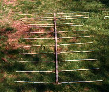
KARAOKE + 4000 SONGS.rar. Antennacraft FM13 Antennacraft FM13 The Antennacraft FM13 is a log-Yagi array with 13 elements on a 137″ boom. Five of the elements are driven. I modeled the antenna with the AO 9.53 Antenna Optimizer program. This image shows the antenna geometry.
This shows segmentation detail for the phasing lines and feedpoint. Blue dots mark analysis segments. The red dot is the feedpoint. Feedpoint Normally I jumper a wire across the feedpoint terminals and place a source at its center. This model is unrealistic for the FM13 because the boom is between the terminals. A Radio Shack balun often used with the antenna has twin-lead split 3″ from the terminal lugs.
I model this geometry instead. The resulting inductive reactance alters SWR, mismatch loss, and forward gain. Modeling Results Calculated performance is for 28 analysis segments per conductor halfwave with additional segments for the phasing lines. Forward gain includes mismatch and conductor losses. F/R is the ratio of forward power to that of the worst backlobe in the rear half-plane.